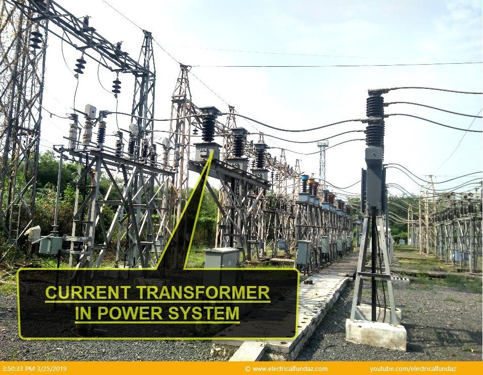
Current Transformer, also called as CT, is an essential equipment in the Power System, mainly in Transmission & Distribution Systems.
What is Current Transformer?
Why is CT required in the Power System?
In HV or EHV Power System, huge amount of current flows through the Primary. If we feed such high currents to Relays/Meters, they will get burnt and so we use a CT, so as to reduce the secondary current in proportion to the to the Primary current, which can then be easily given to Relays or Meters.
Where is it located in the Power System SLD?
What are the Types of CT’s?
On the basis of Primary Winding, CT are classified as below:
- Bar Type CT
- Wound Type CT
On the basis of Tank, CT’s are classified as
- Live Tank type CT: The Core and the Secondary Winding are in the Live Tank Portion.
- Dead tank type CT: The Core and the Secondary Winding are in the Dead Tank Portion of the CT.
On the basis of Function, CT’s are classified into following Types:
- Protection CT: Used for feeding current to the Protection Relays for Protection purpose.
- Metering CT: Used for feeding the current to the Meters for Metering Purpose.
- Summation CT: Used to add 2 or more Primary currents.
Explain the CT Construction?
- Primary Winding: Connected in Series with the Conductor carrying the Current. It has a thick Cross-section Area and consists of a Single Turn.
- Secondary Winding: Load (Meter/Relay) is connected accross the Secondary winding. It consists of Large number of turns and Rated at 1A or 5A. There can be more than one Secondary Windings. There are 3 Cores for 33 KV Feeder and 5 Cores for 132 or 220 KV Feeder/Transformer.
List some of the CT Specifications:
These specifications are given on the name plate and are also called as Name Plate Details of the CT.
- Rated Primary Current: The value of Primary Current which appears on the Name Plate of the Transformer and on which the performance of the CT is based.
- Rated Secondary Current: The Current in the Secondary Circuit, on which the performance of the CT is based. Typical values of Secondary Current are 1A or 5A.
- Rated Burden: It is the apparent power of the Secondary Circuit in Voli-amperes, expressed at the rated secondary current and at a specific Power Factor (0.8 for almost all standards). It is termed as “Burden” to distinguish it from the Primary Load.
- Accuracy Class: For each class, the standards define a maximum allowable current and Phase Displacement Errors for different Load Conditions.
Important features:
Please find below, some Important CT Functions:
- Primary current is not controlled or determined by the conditions of the Secondary Winding Circuit.
- Secondary Current is substantially proportional to Primary Current (under normal operating conditions) and differs in Phase from the Primary Current ideally by Zero Degrees for an appropriate direction of the connections.
What are the CT Tests?
There are following CT Tests:
- Insulation Resistance(IR) Test: Low IRValue indicates abnormal conditions such as presense of moisture, dirt, dust , crack in insulator of CT and degradation of Insulation. For a detail Post/Article on CT Insulation Resistance Test, click on the Link: CT Insulation Resistance Test.
- Tan Delta:
- Knee Point Test:
- Polarity Tests:
- Ratio Test: