-
-
Detecting the incipient weaknesses in HV insulation.
- Predicting the remaining life expectancy of the equipment under test.
- To get the “Benchmark Reference Reading” of equipment when the equipment is new, clean, dry and free from impurities.
-
- Isolation: The Test Equipment (CT/Bushing) needs to be made potential free, by removing the jumpers.Tan Delta Point is to be disconnected from the Earth.
- Setting up the Kit
-
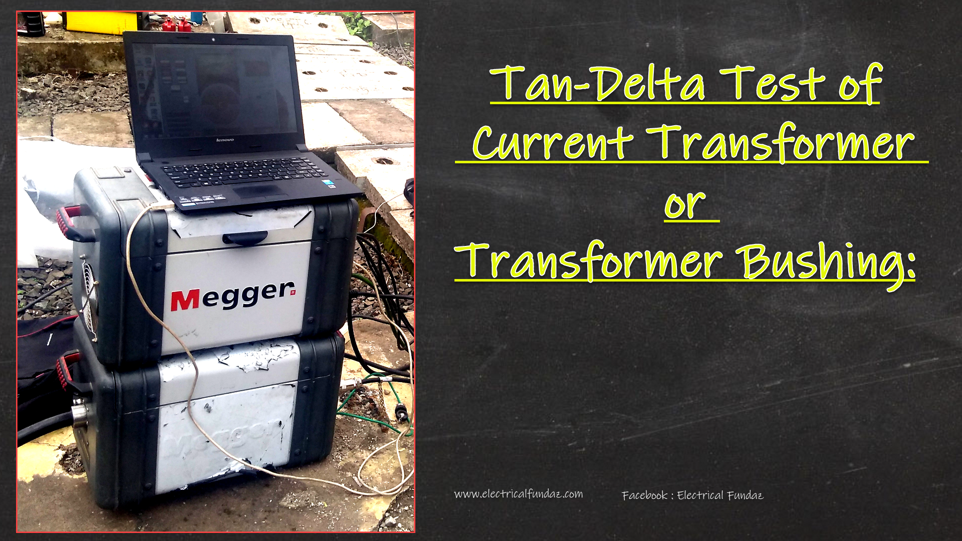
The kit Consists of mainly of 2 units : i) Control Unit which takes command from the Laptop & operates the HV Voltage Unit. ii) HV Voltage Unit houses a Transformer which converts the Single phase 230 V Supply to 2 KV , 5 KV or 10 KV and supplies to Primary.
-
Safety Strobes: The Test will continue, till the safety Stropes are kept operated. If there is accident or something, the safety strobes are left, which stops the test and hence can be used in Emergency case, if someone is about to get electrocuted by the kit.
-
Temperature sensor: They are used to get the Ambient Temperature.
-
Hooter alarm: signals that the Test is in progress.
-
- Connect the HV Lead to the Conductor & LV Lead to the Tan Delta Point.
-
Open the software Delta 4000.Eneter the Voltage.press the safety knobs.Press Start of F2 button.
- Select the Mode UST.
USTTest set connected for Ungrounded Specimen Test mode. This is used when specimen is isolated from earth e.g. Transformer bushing, CTs with test tap, CVTs and CB voltage grading capacitors. The test mode is often used to reduce the effect of stray capacitance losses to ground, and to reduce the effect of interference pickup from energized apparatus.GSTTest set connected for grounded specimen test mode. This is used when specimen do not have two specific points (isolated from ground) for Tan delta measurement e.g.Transformer/Reactor winding, CTs without test tap etc.
- Temperature Correction Factor: Since temperature correction factor for Tan-Delta depends on make, type and alsoaging conditions, the correction factors for different types / makes are different. Hence, no standard temperature correction factors can be applied. In case of violation of Tan-Delta the test results with temperature are to be referred to Manufacturer.
Note down the following Information:
- Place: Write the Name of Substation or Place
-
Feeder/Transformer: Write the Name of Feeder or the Tfr
-
Phase: R/Y/B
-
CT Make, Serial Number & DOM: Say ABB/546544/01.05.2012
-
Test Kit Make & Sr. No: Megger 12121315
- Date of Caliberation of the Test Kit:
-
Atmospheric Condition: Sunny/rainy/ Cloudy Ambient Temperature:
-
Taken by: Name of the Engineer
- Test Voltage: 2KV/5KV/10 KV
| SR No. | Date | Mode | Capacitance (uF) | Tan Delta (%) | Ambient Temp | Corrected TanD | Rate of Rise | Remark |
| 1 | 05.12.18 | UST-R | 1252 | 0.526 | 20 | 0.526 | ||
| 2 | 05.12.18 | UST-R | 1256 | 0.625 | 30 | 0.781 |
- For a New CT it is 0.005 (Max)
- For a CT in Service it is 0.007(Max)
- Rate of Rise of Tan Delta is 0.001/yr (Max)